1.1 Nonspillable
The FirstPower VRLA battery uses an absorbed electrolyte system. All of the electrolyte is absorbed into the positive plates, negative plates, and the separators. Coupled with the use of special sealing epoxies, and long sealing paths for posts, FirstPower VRLA batteries have exceptional leak resistance, and can be used in any position.
1.2 Sealed and Maintenance-free Operation
There is no corrosive gas generation during normal use and no need to check the specific gravity of the electrolyte or to add water during the service life.
1.3 High Quality and High Reliability
The FirstPower VRLA battery has stable and reliable capacity. The battery can withstand overcharge, over discharge, vibration, and shock. To assure this high quality and reliability, the batteries are 100% tested on production line for voltage, capacity, seals and the safety valve are 100% visually inspected before the final assembly process.
1.4 Exceptional Deep Discharge Recovery
FirstPower batteries have exceptional deep discharge recovery and charge acceptance, even after deep or prolonged discharge.
1.5 Low Self-discharge
Because of the use of lead calcium grids alloy and highly purity materials. FirstPower VRLA battery can be stored long periods of time without recharge. The rate of FirstPower VRLA battery self-discharge on open circuit is less than 2% per month at 20oC/68oF to 25oC/77oF.
1.6 Long Service Life
The FirstPower VRLA battery has long life in standby or cyclic service.
1.7 Solid Copper Terminals
Ensures highest current carrying capability.
1.8 Tank-formed Plates
The initial capacity will be 100% and optimize cell voltage balance, due to the tank formation of the plates.
1.9 Computer-aided Design and Manufacturing
Ensures quality products through control of processes and standards.
1.10 UL and CE Recognized.
UL approval, file No. MH28204
CE approval, file No. G2M20201-0102-E-16
3.1. Final Discharging Voltage
The final discharging voltage is the battery terminal voltage in close circuit voltage per cell to which a battery discharging safely and maximize battery life. The higher discharging current is, the lower final discharging voltage of battery should be .
| Discharging Current | Final Discharging Voltage(VPC) |
| Up to 0.1CA | 1.75 |
| 0.11-0.17CA | 1.70 |
| 0.18-0.25CA | 1.67 |
| 0.26-1CA | 1.60 |
| Above 1.1CA | 1.30 |
3.2 Battery Discharging Characteristics:
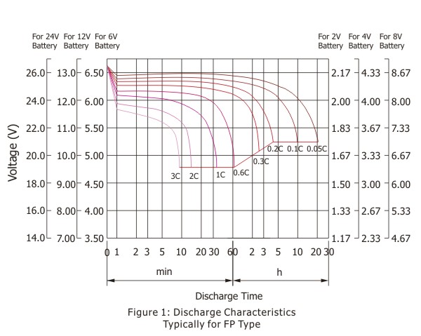
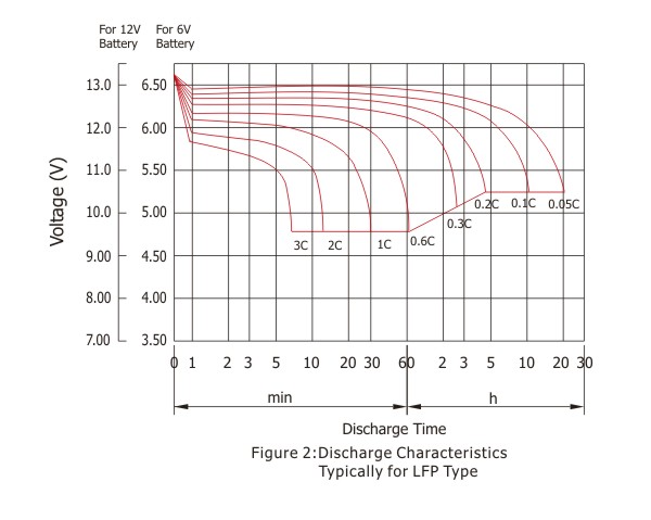
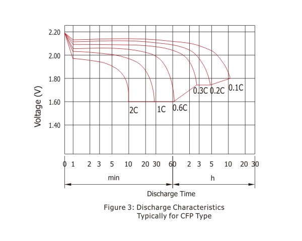
The discharging capacity of battery depends on the discharge rate being used and ambient temperature.
Figure 1,2 and 3 show the different discharging current corresponding to discharging capacity at 20 oC(68oF) to 25oC(77oF) for FP, LFP and CFP types batteries. They show that the rated capacity of a battery is reduced when it is discharged at a value of current that exceeds its 10-hours or 20-hours rate.
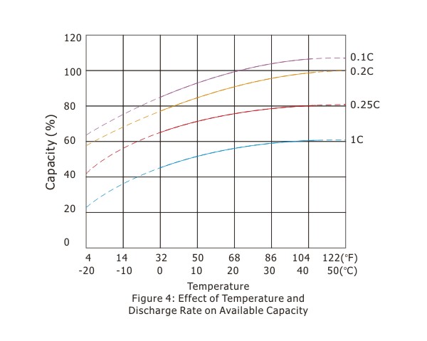
3.3 Temperature Effects in Relation to Battery Capacity.
At a higher temperature, the capacity of battery increases and conversely at a lower temperature, the capacity of battery decreases. Figure 4 shows the effects of different temperature in relation to battery capacity.
Can calculate the batteries' rated capacity as following formula if the ambient temperature of tested battery is not 20oC-25oC(68oF-77oF).
C= Ct
1+k(t-25)
Note:
C: rated capacity
Ct: the tested capacity on t
t: the ambient temperature of
the tested battery
k: the coefficient of temperature. It will be
increased if the discharge current
increased.
k=0.006 20 hours and 10 hours rated
capacity testing,
k=0.01 3 hours and 1 hours rated
capacity testing.
4.1 Charging Methods
Correct charging is one of the most important factors to consider when using valve regulated lead acid batteries. Battery performance and service life will be directly affected by the charging methods.
There are four major methods of charging.
Constant voltage charging.
Constant current charging.
Two stages constant voltage charging. Taper current charging.
4.1.1 Constant Voltage Charging
This is the recommended method of charging for VRLA batteries. It is necessary to closely control the actual voltage to ensure that it is with the limits advised.
Standby service:
2.23-2.30 vpc at 20oC(68oF) to 25oC(77oF)
Cycle service:
2.40-2.50 vpc at 20oC(68oF) to 25oC(77oF)
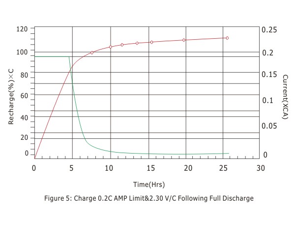
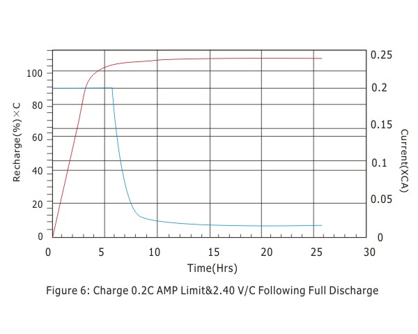
It is suggested that the initial current be set within 0.4CAmps. Figure 5 and 6 indicate the time taken to fully recharge the battery. It is also seen that the charging current is decreased to approx 0.5-4mA/Ah under charging voltage 2.30 vpc, and 3-10mA/Ah under charging voltage 2.40vpc when the battery is fully charged at 20oC(68oF) to 25oC(77oF).
Note: it is necessary to ensure that the voltage is correctly set. The charging voltage set too high will increase the corrosion of the positive plates causing loss of capacity and ultimately shortening the life of the battery.
4.1.2 Constant Current Charging
This method of charging is generally not recommended for VRLA batteries. It is necessary to understand that if the batteries are not removed from the charger as soon as possible after reaching a state of full charge. Considerable damage will occur to the batteries due to over charging. The required recharged capacity is 1.07 to 1.15 times as discharged capacity.
4.1.3 Two Stages Constant Voltage Charging
This method should not be used where the battery and load are corrected in parallel, however, if this method is to be used, it is suggested that the FirstPower technical department be contacted.
4.1.4 Taper Current Charging
This method is not recommended for VRLA batteries, however, if this method is to be used it is suggested that the First Power technical department be contacted.
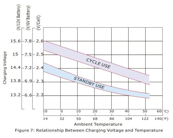
4.2 Effect of Temperature on Charging Voltage
As temperature rises, electrochemical activity in the battery increases. Similarly, as temperature falls, electrochemical activity decreases. Therefore, as temperature rises, charging voltage should be reduced to prevent overcharge, as temperature falls, charging voltage should be increased to avoid undercharge. In general, to assure optimum service life, use of a temperature compensated charger is recommended. The recommended compensation factor for FirstPower VRLA batteries is ±3mV/oC Cell (standby use) and±4mV/oC cell(cyclic use). The standard central point for temperature compensation is 20oC/68oF.
Figure7 shows the relationship between temperatures and charging voltages in both cyclic and standby applications.
4.3 Charging Time
The time required to complete each charge depends on the discharge condition of battery, characteristics of charge used, or the temperature during charge. For cyclic use, using constant voltage charging, this time can be estimated by the following expression at 25oC/77oF.
(1)Discharge current: Larger than 0.25CA
Tch = Cdis/I + 3 ~5
(2)Discharge current: Less than 0.25CA
Tch = Cdis/I + 6 ~10
Tch: time required for charge (hours)
Cdis: ampere-hour discharged before
charge started(Ah)
I : initial charging current(A).
Complete charge time for float service will be slightly more than 24 hours.
Note: The minimum recharge capacity should be 1.02~1.05 times of discharge capacity
Battery life depends on a number of key factors. These include:
Operating temperature of the battery;
Method of charging utilized;
Actual use of the product i.e.: standby or cycle service etc.
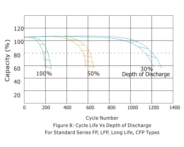
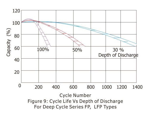
5.1 Cyclic Life
Giving due consideration to the above factors, the actual life of a battery in cycle service is dependent on the depth of discharge of each cycle. The greater the depth of discharge of each cycle, the less the number of cycles available from the battery.
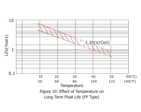
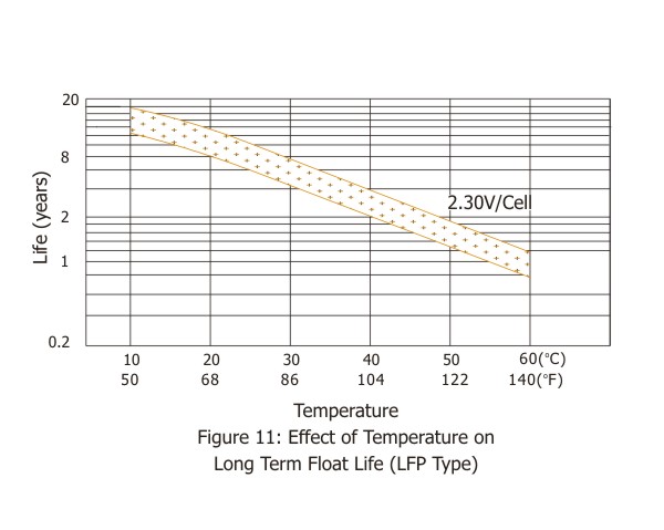
5.2 Standby Life
The estimated life under float service of FP type is 7 years at 20oC/68oF; LFP type is 12 years at 20oC/68oF; CFP type is more than 20 years at 20oC/68oF. The float service life is affected by the factors listed above and the number of discharging, the depth of discharging the battery suffers during its life time. The more discharges suffered and the deeper the discharges, the shorter the battery life. The higher the temperature, the shorter the battery life. If the battery temperature remains at an elevated level for an extended period of time, the expected life is reduced by 50% for each 8 to 10oC of constant temperature above 20oC/68oF.

6.1 General Storage Conditions:
The battery should be stored under the following conditions.
(1) Low humidity
(2) 5 to 122oF(-15 to 50oC)
(3) Clean, and avoid direct sunlight.
6.2 Capacity after Long Term Storage
After long term storage, all batteries deliver less than rated capacity on first cycle. In cyclic application, full capacity may be obtained through several charge/discharge cycles, typically 2-3 cycles.
6.3 Refresh Charge
When batteries are placed in extended storage, it is recommended that they receive a refresh charge at recommended intervals as following;
Refresh charging method:
3 to 5 hours of constant current 0.1C Amps or 12 to 16 hours at constant voltage of 2.45V/cell
| Storage Ambient: | Recommended Interval |
| Below 20 oC(68oF): | 12 months |
| 20 to 30oC(68 to 86oF): | 6 moths |
| 30 to 40oC(86 to 104oF): | 3 moths |
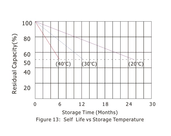
6.4 "Self Life"- typical capacity vs. time
Self-discharge rate is very much dependent on the storage temperature as shown in Figure 13.Lower temperatures allow the battery to be stored for longer periods. (Each ten degree centigrade drop results in a halving of self-discharge rate and doubles storage time.)
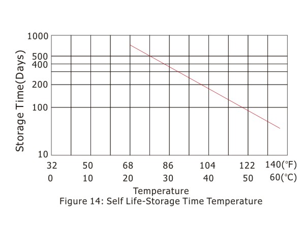
6.5 "Self Life"-storage time vs. temperature
Figure 14 shows the time for the capacity to decrease to 50% of nominal capacity at each temperature during storage. If the storage temperature is known, the graph may be used for finding the most useful recommended refresh charge intervals.
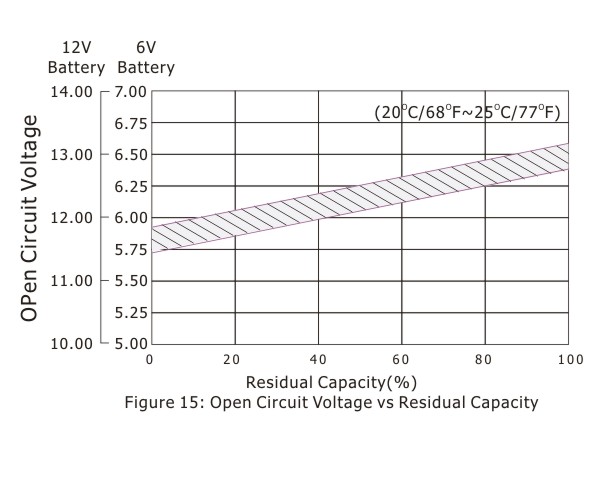
3.4.6 Open Circuit Voltage and Residual Capacity
Residual capacity can be estimated by measuring the open circuit voltage as shown in Figure 15.
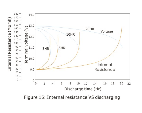
3.5 Battery Internal Resistance
The internal resistance of a battery is lowest when the battery is in a fully charged state. The battery internal resistance will be increased gradually during discharge.Figure 16 shows the changing of internal resistance of FP1272(12V7.2Ah) battery during different rated discharging
The internal resistance of a battery is lowest when the battery is in a fully charged state.
The battery internal resistance will be increased gradually during discharge.
Figure 16 shows the changing of internal resistance of FP1272(12V7.2Ah) battery during different rated discharging
The capacity of a cell/battery is the amount of charge available expressed in Ampere-hours (Ah) if know the discharging current(power) and the discharging time.
The individual battery model specification sheet can be used to determine the minimum battery size
The battery life(cycle service life or floating service life) should be considered for final battery capacity selection.